Engineering Line Types: A Complete Guide for Technical Drawing
Engineering drawings are the universal language of engineering and manufacturing. They communicate the shape, size, features, dimensions, and construction details of a component or product without relying on lengthy explanations.
One of the most important elements of any technical drawing is the line. Different line styles, thicknesses, and patterns are used to communicate different types of information. For example, a continuous thick line may represent a visible edge, while a dashed line can indicate a hidden feature.
Understanding engineering line types is essential for students, CAD designers, draftsmen, mechanical engineers, architects, and manufacturing professionals.
In this guide, we will explain the most commonly used engineering line types, their applications, and why they are important in technical drawing.
What Are Engineering Line Types?
Engineering line types are standardized graphical representations used in technical and engineering drawings. Each line has a specific purpose and helps the reader understand the geometry and manufacturing requirements of a component.
Lines can differ in:
Thickness
Continuity
Pattern
Length of dashes
Direction
Application
Engineering drawing standards define how these lines should be used so that drawings can be understood consistently by designers, manufacturers, engineers, and technicians.
According to engineering-drawing standards, different line types are assigned specific applications such as visible outlines, hidden edges, dimensions, center lines, cutting planes, and section views.
Why Are Line Types Important in Engineering Drawing?
Using the correct line type is important because a technical drawing must communicate information clearly and accurately.
Incorrect use of line types can lead to:
Misinterpretation of component geometry
Manufacturing errors
Incorrect dimensions
Confusion between visible and hidden features
Problems during inspection
Increased production costs
For example, if a hidden edge is represented using a continuous object line instead of a dashed line, the person reading the drawing may misunderstand the actual shape of the component.
Therefore, learning engineering line types is one of the first steps toward becoming proficient in technical drawing and CAD drafting.
Common Types of Lines in Engineering Drawing
There are several line types used in engineering and technical drawings. The following are among the most important ones.
1. Continuous Thick Line – Visible/Object Line
A continuous thick line is primarily used to represent the visible outlines and visible edges of an object.
It is also commonly called an object line.
Applications
Continuous thick lines are used for:
Visible outlines
Visible edges
External boundaries
Clearly visible features of a component
Example
Imagine a rectangular mechanical component with a hole. The outside boundary that you can directly see is normally represented using a continuous thick line.
The purpose is to make the actual shape of the object immediately recognizable.
2. Continuous Thin Line
A continuous thin line is one of the most frequently used lines in technical drawings.
It is thinner than the main object line and is used for several supporting purposes.
Applications
Continuous thin lines can represent:
Dimension lines
Extension lines
Projection lines
Leader lines
Hatching or section lines
Construction-related information
These lines provide additional information without visually overpowering the main geometry.
3. Hidden Line
A hidden line represents an edge or feature that exists on the object but cannot be directly seen from the current viewing direction.
Hidden lines are normally represented using a series of evenly spaced dashes.
Applications
Hidden lines are used to show:
Internal holes
Hidden slots
Internal steps
Edges behind a surface
Features that are not visible in the selected view
Example
If a cylindrical hole passes through a block but the hole is not visible from the front view, its hidden edges can be represented using dashed lines.
Correct use of hidden lines helps the reader understand the three-dimensional structure of a component from a two-dimensional drawing.
4. Center Line
A center line is used to identify the center or axis of symmetrical and circular features.
It is generally represented using a chain pattern consisting of long and short segments.
Applications
Center lines are commonly used for:
Circular holes
Cylinders
Arcs
Shafts
Symmetrical components
Axes of rotation
Pitch circles
For example, when drawing a circular hole, the center line helps identify the exact center of the hole and its position relative to other features.
Center lines are particularly important when creating dimensions and aligning features.
5. Dimension Line
A dimension line communicates the size or distance of a feature.
Dimension lines are generally thin and are terminated by arrowheads or other standardized terminators.
Applications
They are used to indicate:
Length
Width
Height
Diameter
Radius
Distance between features
Angles
For example:
100 mm
The dimension line indicates the distance represented by the numerical dimension.
Dimension lines should be placed clearly so that dimensions can be read without confusing them with object geometry.
6. Extension Line
An extension line extends from the feature being dimensioned to the dimension line.
It allows the dimension to be positioned away from the actual object while clearly identifying the feature to which the measurement applies.
Applications
Extension lines are commonly used for:
Linear dimensions
Angular dimensions
Locating features
Connecting object geometry to dimension information
They are normally drawn as thin continuous lines.
7. Leader Line
A leader line connects a note, symbol, dimension, or specification to a particular feature of an object.
It is particularly useful when there is not enough space to place information directly beside the feature.
Applications
Leader lines can identify:
Hole specifications
Surface finish
Welding information
Material requirements
Manufacturing notes
Special features
A leader line may terminate with an arrowhead, dot, or another appropriate terminator depending on the application and drawing standard.
8. Section or Hatching Lines
When an object is cut by an imaginary plane to reveal its internal construction, the resulting sectional area is commonly represented using hatching lines.
Hatching lines are thin, continuous, and usually drawn at a consistent angle and spacing.
Applications
They are used to show:
Cut surfaces
Internal construction
Sectional views
Material areas
For example, if a machine component is cut through the middle, hatching can indicate the surfaces exposed by the imaginary cut.
Proper spacing and consistency are important for clear sectional drawings. Engineering-drawing guidance recommends maintaining adequate spacing between hatching lines.
9. Cutting Plane Line
A cutting plane line identifies where an imaginary section is taken through an object.
It helps the reader understand:
Where the object has been cut
The direction from which the section is viewed
Which sectional view corresponds to the cutting plane
Cutting plane lines are particularly important in mechanical and architectural drawings where internal features need to be shown clearly.
10. Break Line
Break lines are used when a portion of an object is removed from the drawing to make a long or complicated component easier to represent.
There are commonly two forms:
Short Break Line
A short break line is generally represented using a freehand irregular line.
It is useful for showing a small interruption or break in an object.
Long Break Line
A long break can be represented using a thin line with a zigzag pattern.
It is useful when a long component has a uniform shape and drawing its complete length would unnecessarily occupy drawing space.
11. Phantom Line
A phantom line is generally represented using a long-short-short-long pattern.
It can be used to represent features such as:
Alternate positions of moving components
Adjacent parts
Extreme positions
Repeated details
Certain reference information
Phantom lines are particularly useful in assembly and mechanical drawings where movement or alternate positions need to be communicated.
12. Construction Lines
Construction lines are light, thin lines used during the process of creating a drawing.
They help the designer construct geometry accurately before producing the final drawing.
Applications
Construction lines may be used for:
Geometric construction
Alignment
Finding centers
Creating reference points
Establishing angles
Developing shapes
In manual drafting, construction lines may eventually be erased. In CAD software, they can often be placed on separate layers or assigned appropriate drafting properties.
Engineering Line Types: Quick Reference Table
| Line Type | Appearance | Main Purpose |
|---|---|---|
| Continuous Thick | Solid, thick | Visible outlines and edges |
| Continuous Thin | Solid, thin | Dimensions, extensions, leaders, projections |
| Hidden Line | Short dashes | Hidden edges and features |
| Center Line | Long-short pattern | Centers and axes |
| Dimension Line | Thin with terminators | Showing measurements |
| Extension Line | Thin continuous | Extending features for dimensions |
| Leader Line | Thin with arrow/dot | Notes and feature identification |
| Section/Hatching Line | Thin, angled | Cut surfaces |
| Cutting Plane Line | Heavy chain-type line | Indicates section location |
| Break Line | Freehand or zigzag | Shortening or interrupting objects |
| Phantom Line | Long-short-short pattern | Alternate positions and adjacent features |
| Construction Line | Very thin/light | Geometric construction |
The exact appearance and application of line types should follow the applicable drafting standard used for the project. Standard engineering-drawing references distinguish continuous, dashed, chain, and double-dashed line forms for different applications.
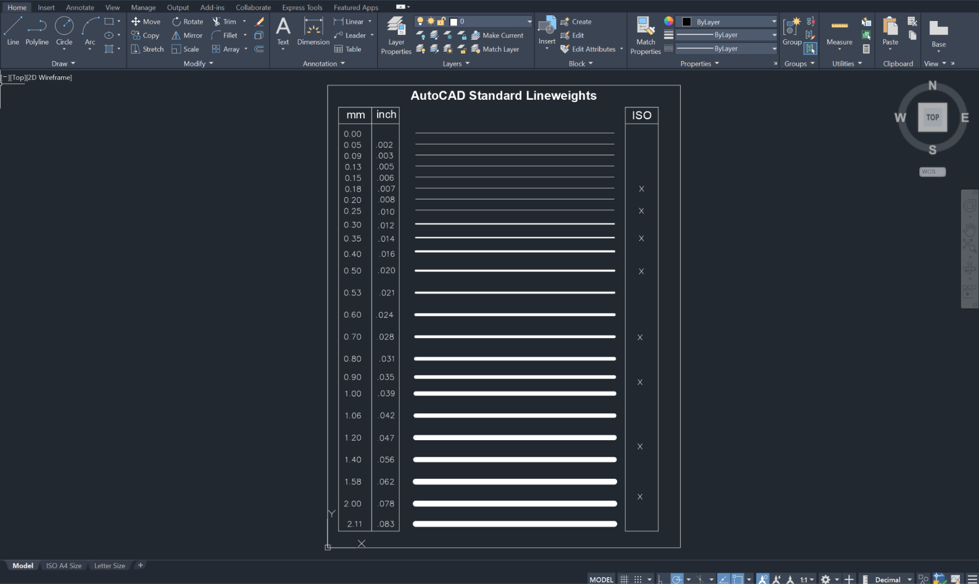
Line Thickness in Technical Drawing
Line thickness is another important part of engineering drawing.
Generally, drawings use a combination of thick and thin lines to create visual hierarchy.
For example:
Object outlines → thicker
Dimension lines → thinner
Extension lines → thinner
Center lines → thinner
Hidden lines → thinner or standardized according to the selected drafting standard
The important principle is consistency.
All views of a component drawn at the same scale should maintain a consistent range of line thicknesses. Engineering-drawing guidance also recommends using a consistent approach to line types and thickness throughout a drawing.
Engineering Line Types in CAD Software
Modern engineering drawings are frequently created using CAD software such as:
AutoCAD
SolidWorks
CATIA
Creo
Fusion
Revit
Inventor
CAD software makes it easier to control line types, line weights, layers, colors, and drawing standards.
For example, in AutoCAD, different layers can be assigned for:
Object lines
Hidden lines
Center lines
Dimensions
Construction geometry
Section lines
This makes complex drawings easier to manage and edit.
Common Mistakes When Using Engineering Lines
Beginners often make mistakes when creating technical drawings.
1. Using the Same Line Thickness Everywhere
Using identical line weights can make a drawing difficult to read.
2. Incorrect Hidden Lines
Hidden features should not normally be represented using visible object lines.
3. Missing Center Lines
Circular and symmetrical features often require center or axis information.
4. Confusing Dimension and Extension Lines
Dimension lines communicate measurements, while extension lines identify the geometry being measured.
5. Inconsistent Line Types
A drawing should maintain consistent drafting conventions throughout all views.
6. Overusing Hidden Lines
Too many hidden lines can make a drawing unnecessarily complicated. When appropriate, a sectional view may communicate internal details more clearly.
Engineering Line Types and Technical Drawing Standards
Engineering drawings should follow the relevant standards used by the organization, industry, or country.
Standards help establish consistent conventions for:
Line types
Line thickness
Dimensioning
Symbols
Section views
Projection methods
Drawing layouts
For example, engineering-drawing educational material based on Indian standards describes multiple line categories, including continuous, dashed, and chain lines, with specific applications for visible edges, hidden edges, center lines, cutting planes, and other features.
Always check the specific standard required for your project rather than relying only on general drafting conventions.
How to Learn Engineering Drawing Effectively
If you are a beginner, the best approach is to learn line types along with practical drawing exercises.
A useful learning sequence is:
Step 1: Learn Basic Geometry
Understand:
Lines
Circles
Arcs
Angles
Polygons
Geometric constructions
Step 2: Understand Line Types
Practice identifying:
Visible lines
Hidden lines
Center lines
Dimension lines
Extension lines
Section lines
Step 3: Learn Orthographic Projection
Practice creating:
Front views
Top views
Side views
Step 4: Practice Dimensioning
Learn how to correctly place dimensions, extension lines, and leader lines.
Step 5: Move to CAD
Once the fundamentals are clear, practice creating the same drawings using CAD software.
Step 6: Work on Real Projects
Create practical drawings such as:
Mechanical components
Machine parts
Brackets
Shafts
Flanges
Assemblies
Building plans
This combination of theory and practical work helps develop real drafting skills.
Conclusion
Engineering line types are much more than simple lines on a drawing. Each line communicates specific information about the shape, size, position, construction, or internal features of an object.
Understanding the difference between visible lines, hidden lines, center lines, dimension lines, extension lines, leader lines, section lines, cutting plane lines, and break lines is essential for anyone working with technical drawings.
Whether you are an engineering student, CAD designer, draftsman, mechanical designer, architect, or manufacturing professional, mastering line types will help you create and interpret technical drawings more accurately.
At CadCraftTech, developing practical CAD and engineering-design skills can help learners move from basic drafting concepts toward professional technical drawing and design workflows. The platform's learning paths include CAD drafting, mechanical design, and BIM-oriented progression.
Start with the fundamentals, practice regularly, and gradually apply engineering drawing standards to real-world CAD projects.
Comments (1)
this is best option
thank you for update.